
Basic Microcode Control: Simple Microcoded Operations
Revised to included better register functions.
Goal
To automate the processes of of the simple computer created in the last lab using micro coding.
Step 1 – Verify, and update your system from Lab 6
Below is a system similar to what you should have after lab 6. Verify that your system is capable of everything this system can do. If not, update your system.
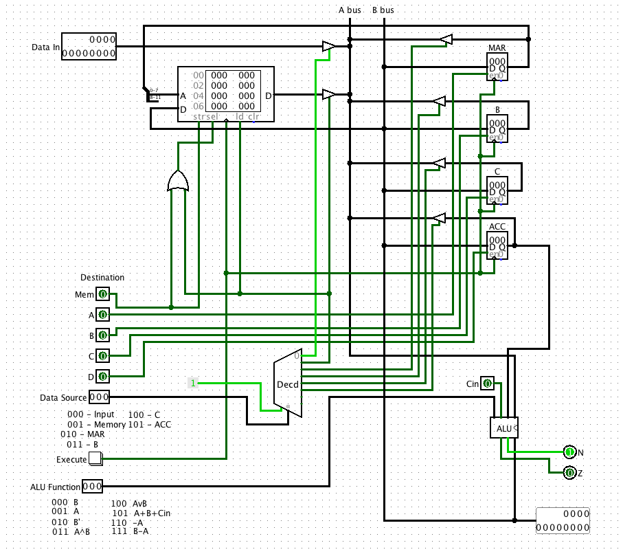
To Do:
- Modify your Lab 6 system to look like the system above.
- How can you clear the accumulator?
Step 2 – Improving the system with better registers (counters)
Before we move on we are going to learn how to use a NEW device called a counter. A counter is like a register, e.g. it can load and hold data, and be cleared, but it can also count up, and down.
Below is a simple circuit to count up from 0 to 255:
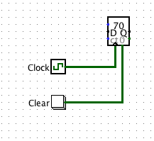
The enable must be on for the counter to count. Note that the counter can be set to trigger with a clock on the rising edge, or falling edge. The counter also has an 8-bit D (Data) input so a number can be loaded into it. Also, the 0 input clears the counter (asynchronously) back to zero. The load and count bits control this function.
To Do
- Build the counter circuit above. Try it out.
- Paste an image of your clock in the lab report.
- What is the purpose of the carry out bit? How could it be useful?
- Below is a table that shows the functions of the counter based on the inputs. Finish the table to explain how the counter works.
We are going to use counters for two purposes in this lab – first to improve the register functions of our simple system (add clear, increment and load operations), and also to beuild a sequencer for our microprogram.
Consider a new register design below:
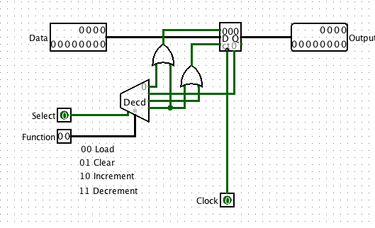
Build this as a sub-circuit and call it Register. Try it out. Now you can select the register, and give it a function. Make sure this works.
To Do:
- Build the register as a subcircuit. It will need to be a 12-bit version like above.
- Test it completely.
- Modify your previous system to use this kind of register. You will need a new 2-bit input “Register Function”.
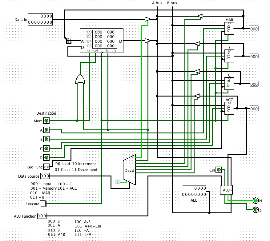
- Make a copy of your system and paste it into your lab report.
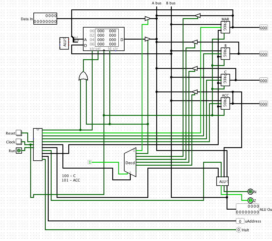
The circuit you make should look like this:
Step 3 – Adding a micro-Sequencer
In lab 6 the operation of the system was completely manual. In order to work through a series of steps, the operations had to be selected manually step by step.
Consider that rather than entering these values manually, we could put the bits in a ROM memory, and step through the operations one location at a time.
Consider that the inputs to the circuit are merely a series of bits from a ROM:
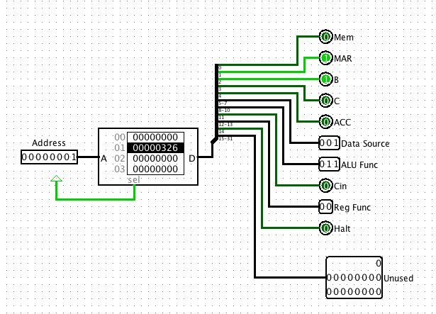
The bits of the ROM can be assigned specific function selections:
| Ununsed | Halt | Reg Func | Cin | ALU Func | Data Source | ACC | C | B | MAR | Mem |
|---|---|---|---|---|---|---|---|---|---|---|
| 31-12 | 14 | 12-13 | 11 | 8-10 | 5-7 | 4 | 3 | 2 | 1 | 0 |
The bit fields are defined as follows:
ALU Functions
| Bits | Operation |
|---|---|
| 000 | ACC |
| 001 | Reg |
| 010 | ACC’ |
| 011 | Reg ^ ACC |
| 100 | Reg V ACC |
| 101 | Reg + ACC + Cin |
| 110 | -Reg |
| 111 | ACC-Reg |
Data Source
| Bits | Source |
|---|---|
| 000 | Input |
| 001 | Memory |
| 010 | MAR |
| 011 | B |
| 100 | C |
| 101 | ACC |
Reg Func
| Bits | Func |
|---|---|
| 00 | Load |
| 01 | Clear |
| 10 | Increment |
| 11 | Decrement |
Counter for microprogram ROM
In order to make a microseqencer we need to generate addresses for a ROM memory that will hold the program. This can be done with a Logisim 8-bit counter. For now we use a push button rather than a clock. We can use an 8-bit counter.
Building the complete microsequencer
Below is microsequencer – a simple device to send the signals to the processing system.
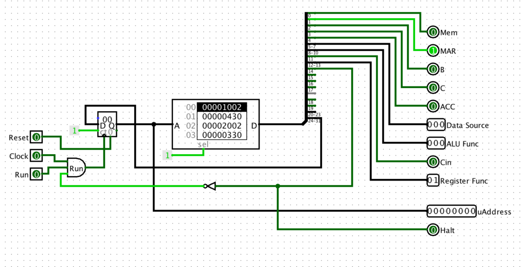
Below is the Microsequencer in place:
We can assign the bits of the ROM to specific functions. We are using 32 bits for future expansion. First let us consider a simple micro-program to add the contents of register B to register C, and put the result in ACC.
The table below is filled in to the values of the micro instructions:
| Unused | Halt | Reg Func | Cin | ALU Func | Data Source | ACC | C | B | MAR | Mem | Operations | Binary | Hex Value |
|---|---|---|---|---|---|---|---|---|---|---|---|---|---|
| 31-12 | 14 | 12-13 | 11 | 8-10 | 5-7 | 4 | 3 | 2 | 1 | 0 | |||
| 0000000000000000000 | 0 | 00 | 0 | 100 | 011 | 1 | 0 | 0 | 0 | 0 | ACC<-B | 00000000000000000000010001110000 | 00000470 |
| 0000000000000000000 | 0 | 00 | 0 | 011 | 100 | 1 | 0 | 0 | 0 | 0 | ACC<-ACC+C+Cin | 00000000000000000000001110010000 | 00000390 |
| 0000000000000000000 | 1 | 00 | 0 | 000 | 000 | 0 | 0 | 0 | 0 | 0 | Halt | 00000000000000000100000000000000 | 00004000 |
If we select the ROM in the micro-sequencer we can select edit contents and put 00000470 in location 0, and 00000390 in location on.
Now if we hit reset, and then hit the clock button twice we can step through the instructions.
To Do
- Modify your machine from the last lab to include the micro-sequencer. Build the micro-sequencer first as a sub-circuit. Then connect it you your main system, and test it out.
- Get it to work with the simple program to add B and C above.
- What happens if you don’t include the Halt instruction at the end?
- Take screen shots of the main machine, and the micro-sequencer, and include in Lab report.
Step 3 – Writing larger programs.
Writing the microcode words is obviously extremely tedious. To avoid the probably insanity I have created a simple Javascript program to automatically assemble micro-instructions for you. The program is VERY simple. It merely ORs together the selected bits to form a bit string and then converts it to HEX for easy copy and pasting into your machines.
The Microcode generator: https://cs.jimskon.com/class/arch/microcode1.html
Note that you select the functions, and the micro-instruction is generated.
Lets try to write a program that sums the first 4 numbers in memory, and puts the result in memory location 5. For example, suppose:
| Memory Address | Contents |
|---|---|
| 0 | 0x2 |
| 1 | 0x5 |
| 2 | 0x6 |
| 3 | 0x3 |
| 4 | 0x0 |
What we want the program to do is add M[0]+M[1]+M[2]+M[3]=0x2+0x5+0x6+0x3 = 0x10. (or 16 decimal)
Here is a program:
| Operation | Comment | Code |
|---|---|---|
| MAR <- 0 | Set up to read memory location 0 | 1002 |
| ACC <- Mem | Get M[0] | 30 |
| MAR++ | Increment MAR | 2040 |
| ACC <- ACC + Mem | Add M[1] to ACC. | 330 |
| MAR++ | Increment MAR | 2040 |
| ACC <- ACC + Mem | Add M[2] to ACC. | 330 |
| MAR++ | Increment MAR | 2040 |
| ACC <- ACC + Mem | Add M[3] to ACC. | 330 |
| MAR++ | Increment MAR | 2040 |
| Mem <- ACC | Save Sum to M[4] | a1 |
| Halt | All done | 8000 |
The ROM image should look like:
v2.0 raw
1002 30 2040 330 2040 330 2040 330
2040 a1 8000Code language: CSS (css)
Copy and paste the ROM image to a text file. Then go to the microcode ROM on the system, and load the file into the ROM. Make sure it works.
To Do
- Get the Machine to run the program above.
- Paste a picture of the machine and the sequencer into the lab report after the program has run correctly
- Write a program to do the following:
M[0] ^ Input v M[1] -> M[2] where Input = 0x3, M[0] = 0x5, M[1]=0x8.
Start by making a table like above. Show the operations, and then convert the operations into HEX. - Use the microprogram generator to create the ROM image. Load the ROM image into the ROM.
- Test the program out.
- Show of picture of the machine after running the program, and the ROM file that you created.
Final Questions
- Consider if you wanted to write code to multiple two arbitrary numbers. Could you do it? How, or why not?
- What if you wanted to average an array of numbers in memory, where the array size was specified by another word in memory?
- In general, what is missing from this too allow more general programming?