
In this lab you will learn the basics of Logisim.
Step 0: Obtaining Logisim
To get started, follow these instructions to get a copy of Logisim on your working machine. 1. Logisim requires Java 5 or later. If you do not already have it on your computer, Java is available from java.sun.com.
2. Download Logisim here: Logisim, or from the SourceForge page. Follow the download link from here: Logisim Web Page
3. To execute the program:
U On Windows and MacOS systems, you will likely be able to start Logisim by double-clicking the JAR file. If that doesn’t work, or if you use Linux, you can type “java -jar logisim-XX.jar” at the command line.
Step 1:
Review the Logisim Tutorial Above. You are to complete the tutorial up to the “Libraries and Attributes” sections. Follow each step and try it for yourself. Take screenshots of each major completed activity and include it in your lab report.
Step 2:
Consider the following block diagram for a seven segment display:
- 7-segDisplay.circ: 7 Segment Test Circuit
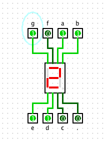
Note that there are 7 inputs to the 7-segment LED display. A one (1) on any input line lights the matching segment. A zero (0) input turns the segment off.
Thus a “4” can be displayed by putting the following values into the 7-Segment LED display inputs:
0 -> a, d, e
1 -> b, c, f, g
Create a test circuit with a 7-segment LED display. and make it display a 4 using this (crude) method. Copy and paste the circuit into your lab report.
Step 3:
Consider the block diagram of the “BCD to 7 Segment Decoder”. This is a circuit that takes binary values from 0 to 9, and sends the right signals to the Display to show the right number.
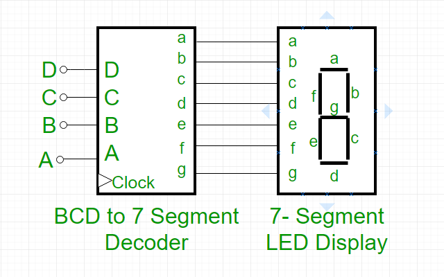
BCD stands for “Binary Coded Decimal”.
Below is a incomplete truth table showing the decimal number, the binary version of the decimal number, ABCD, the corresponding inputs to the decoder, and abcdefg, the outputs needed by the decoder to light the LED correctly. It only shows the proper outputs for an input of 0, and it also shows the column for how each number affects segment e.
| Decimal # | Binary | A | B | C | D | a | b | c | d | e | f | g |
| 0 | 0000 | 0 | 0 | 0 | 0 | 1 | 1 | 1 | 1 | 1 | 1 | 0 |
| 1 | 0001 | 0 | 0 | 0 | 1 | 0 | ||||||
| 2 | 0010 | 0 | 0 | 1 | 0 | 1 | ||||||
| 3 | 0011 | 0 | 0 | 1 | 1 | 0 | ||||||
| 4 | 0100 | 0 | 1 | 0 | 0 | 0 | ||||||
| 5 | 0101 | 0 | 1 | 0 | 1 | 0 | ||||||
| 6 | 0110 | 0 | 1 | 1 | 0 | 1 | ||||||
| 7 | 0111 | 0 | 1 | 1 | 1 | 0 | ||||||
| 8 | 1000 | 1 | 0 | 0 | 0 | 1 | ||||||
| 9 | 1001 | 1 | 0 | 0 | 1 | 0 |
Notice that the 0 inputs turns on all the segments BUT “g”, which is the center segment and must be off.
Also look down the “e” column. This shows all the times the “e” segment must be turned on, e.g. for 0, 2, 6, 8 only.
Fill in the rest of the table in your lab report.
Step 4:
Now consider a truth table constructed for only the “e” segment:
| A | B | C | D | e segment |
| 0 | 0 | 0 | 0 | 1 |
| 0 | 0 | 0 | 1 | 0 |
| 0 | 0 | 1 | 0 | 1 |
| 0 | 0 | 1 | 1 | 0 |
| 0 | 1 | 0 | 0 | 0 |
| 0 | 1 | 0 | 1 | 0 |
| 0 | 1 | 1 | 0 | 1 |
| 0 | 1 | 1 | 1 | 0 |
| 1 | 0 | 0 | 0 | 1 |
| 1 | 0 | 0 | 1 | 0 |
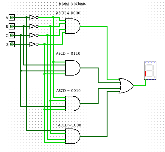
Now consider a circuit to implement the truth table above. Look in the table and see that the a segment is “1” in three cases, when ABCD is 0000, 0010, 0110, and 1000. We can thus create 4 small curcuits for each of these cases:
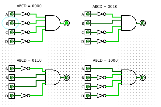
eSegmentIndividual.circ: eSegmentIndividual.circ
These four circuits can be combined into a larger circuits by ORing the results!
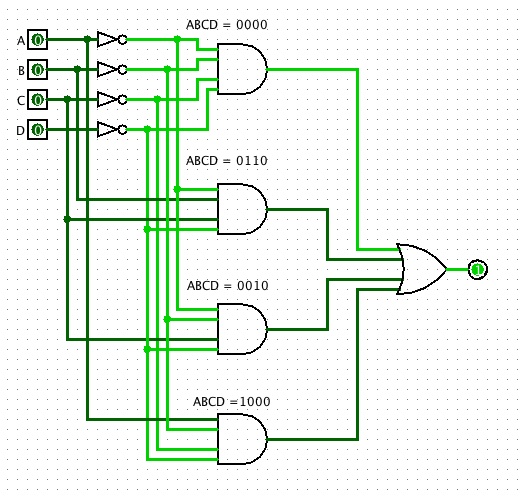
eSegmentcomplete.circ: eSegmentcomplete.circ
Thus the circuit above can be connected to the appropriate segment.
- eSegmentDisplayLED.circ: eSegmentDisplayLED.circ
Create and test this circuit.
Step 5:
Read from the tutorial PDF the “Designing a sub circuit” section. Take the step for circuit and create a Macro for it. Then use it to control the 7-Segment display. Below is a new circuit that does exactly what the circuit above does.
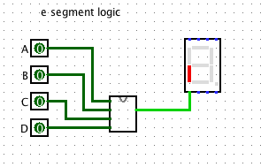
eSegmentSubcircuit.circ: eSegmentSubcircuit.circ
Step 6:
Now make a truth table, and a circuit for each of the other 6 segments. Turn each of these into a template. The inputs should all be connect to the same four inputs. Test out the circuit on all 10 values. Clip the circuit and paste into your Lab Report. Try to keep you circuits orderly and easy to read.