
Case Scenario: Software Development Lifecycle
Imagine managing a software development project with the following 15 tasks. Each task depends on the completion of one or more preceding tasks, ensuring a logical flow from initiation to deployment and maintenance.
List of Tasks and Dependencies
- Task A: Define Project Scope
- Task B: Gather Requirements
- Task C: Analyze Requirements
- Task D: Create Design Specifications
- Task E: Develop Frontend
- Task F: Develop Backend
- Task G: Set Up Development Environment
- Task H: Integrate Frontend and Backend
- Task I: Develop API Endpoints
- Task J: Write Unit Tests
- Task K: Perform Integration Testing
- Task L: Conduct System Testing
- Task M: User Acceptance Testing (UAT)
- Task N: Deploy to Production
- Task O: Monitor and Maintain
Dependencies Between Tasks
- Task A → Task B
- Task B → Task C
- Task C → Task D
- Task D → Task E
- Task D → Task F
- Task G → Task E
- Task G → Task F
- Task E → Task H
- Task F → Task I
- Task I → Task H
- Task H → Task J
- Task J → Task K
- Task K → Task L
- Task L → Task M
- Task M → Task N
- Task N → Task O
We can visually represent it like this:
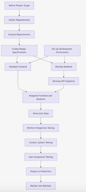
Problem: Can we write program that takes a set of tasks and dependancies, and create a possible order in which to complete the project assuming we can do only on task at a time? E.g. how do we convert a DAG into a well-ordered list?
To start, we could texually represent the dependencies like this:
A[Define Project Scope] --> B[Gather Requirements]
B --> C[Analyze Requirements]
C --> D[Create Design Specifications]
D --> E[Develop Frontend]
D --> F[Develop Backend]
G[Set Up Development Environment] --> E
G --> F
E --> H[Integrate Frontend and Backend]
F --> I[Develop API Endpoints]
I --> H
H --> J[Write Unit Tests]
J --> K[Perform Integration Testing]
K --> L[Conduct System Testing]
L --> M[User Acceptance Testing (UAT)]
M --> N[Deploy to Production]
N --> O[Monitor and Maintain]
Can we write a program to read in the text above, and produce something like this (a well-ordered list):
A [Define Project Scope]
B [Gather Requirements]
G [Set Up Development Environment]
C [Analyze Requirements]
D [Create Design Specifications]
E [Develop Frontend]
F [Develop Backend]
I [Develop API Endpoints]
H [Integrate Frontend and Backend]
J [Write Unit Tests]
K [Perform Integration Testing]
L [Conduct System Testing]
M [User Acceptance Testing (UAT)]
N [Deploy to Production]
O [Monitor and Maintain]
Directed Acyclic Graphs (DAGs)
Directed Acyclic Graphs (DAGs) are powerful data structures used to model relationships where direction and the absence of cycles are essential. They are widely applicable in various fields, including computer science, project management, and data processing.
The earlier diagram is a DAG.
1. Understanding DAGs
What is a DAG?
- Directed: Each edge has a direction, indicating a relationship from one node to another.
- Acyclic: The graph does not contain any cycles, meaning there’s no way to start at a node and return to it by following the directed edges.
Common Uses of DAGs
- Task Scheduling: Representing dependencies between tasks.
- Version Control Systems: Modeling commits where each commit points to its predecessors.
- Data Processing Pipelines: Structuring stages where data flows in one direction.
- Expression Trees: Representing mathematical expressions.
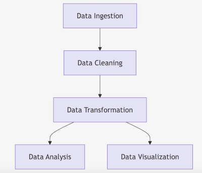
2. Example: Task Dependency DAG
Description: A common use of DAGs is to represent tasks with dependencies. For example, in project management, certain tasks must be completed before others can begin.
Consider the following set of tasks on a progect:
A. Data Ingestion
B. Data Cleaning
C. Data Transformation
D. Data Analysis
E. Data Visualization
With the following dependancies:
- Data Ingestion –> Data Cleaning
- Data Cleaning –> Data Transformation
- Data Transformation –> Data Analysis
- Data Transformation –> Data Visualization

This could be coded like this in a text file:
- A[Data Ingestion] –> B[Data Cleaning]
- B –> C[Data Transformation]
- C –> D[Data Analysis]
- C –> E[Data Visualization]
Assuming you can only do one task as a time, what is an ordering the will work for this project?
Here is another example.

This could be represented by this:
- A[Project Planning] –> B[Design Architecture]
- A –> C[Obtain Permits]
- A –> D[Site Survey]
- B –> E[Site Preparation]
- C –> E
- D –> E
- E –> F[Foundation]
- F –> G[Framing]
- G –> H[Roofing]
- G –> I[Electrical Installation]
- G –> J[Plumbing Installation]
- I –> K[HVAC Installation]
- J –> K
- K –> L[Interior Finishing]
- K –> M[Exterior Finishing]
- L –> O[Final Inspection]
- M –> O
- N[Landscaping] –> O
What data structure can we use to represent such a graph?
Representing a graph

How would you choose which representation to use?
Do you need to use a linked list to represent an adjacency list?
Once we have a representation of a di-graph, how do we convert it into a well ordered list?
Topological Sort
1.1. What is Topological Sort?
- Definition: Topological Sort is a linear ordering of vertices in a DAG where for every directed edge
uv, vertexuprecedes vertexvin the ordering. - Key Characteristics:
- Applicability: Only applicable to DAGs (graphs without cycles).
- Multiple Valid Sorts: A DAG can have multiple valid topological orderings.
- Use Cases: Task scheduling, course prerequisite ordering, build systems, etc.
1.2. Use a Stack
- LIFO Property: Stacks operate on a Last-In-First-Out (LIFO) principle, making them ideal for storing vertices in the reverse order of their completion during DFS.
- Efficient Storage: As DFS explores deeper into the graph, vertices are pushed onto the stack once all their dependencies have been processed, ensuring the correct topological order when popped.
2. Topological Sort Using DFS and a Stack
2.1. High-Level Overview
- Initialization:
- Start with an empty stack.
- Maintain a visited set to track processed vertices.
- DFS Traversal:
- Perform DFS on each unvisited vertex.
- For each vertex, recursively visit all its adjacent (dependent) vertices.
- Stack Operations:
- After visiting all adjacent vertices of a vertex, push the vertex onto the stack.
- This ensures that vertices with no outgoing edges are at the top of the stack.
- Generating the Order:
- Pop all vertices from the stack to get the topological ordering.
2.2. Step-by-Step Explanation
Let’s break down the algorithm with an example DAG:
Example DAG:
A --> B
A --> C
B --> D
C --> D
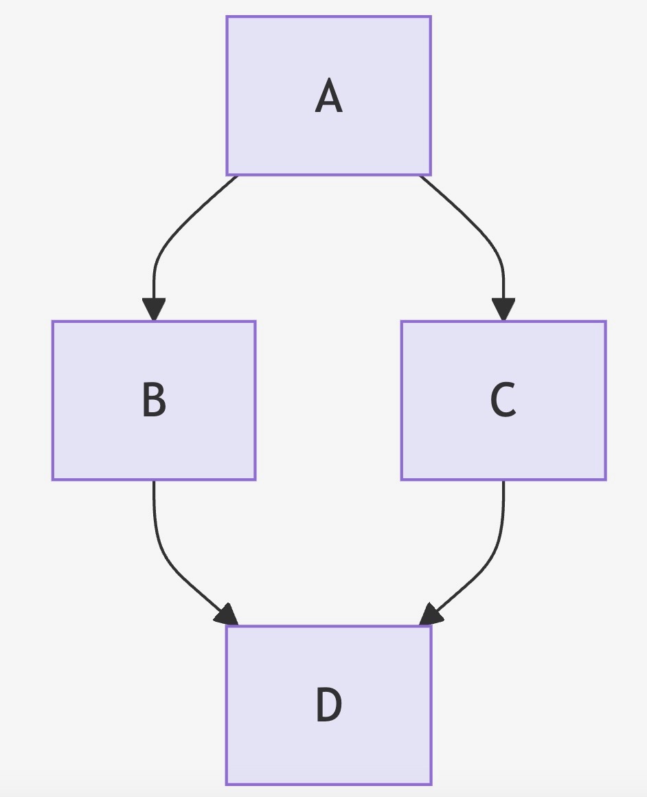
Topological Sort Steps:
- Start with Vertex A:
- Mark A as visited.
- Visit A’s neighbors: B and C.
- Visit Vertex B:
- Mark B as visited.
- Visit B’s neighbor: D.
- Visit Vertex D:
- Mark D as visited.
- D has no neighbors.
- Push D onto the stack.
- Back to Vertex B:
- All neighbors of B are processed.
- Push B onto the stack.
- Back to Vertex A:
- Next neighbor: C.
- Visit Vertex C:
- Mark C as visited.
- Visit C’s neighbor: D.
- D is already visited.
- Push C onto the stack.
- Back to Vertex A:
- All neighbors of A are processed.
- Push A onto the stack.
- Finalize the Order:
- Pop vertices from the stack: A, C, B, D.
- Reverse the order to get the topological sort: A, B, C, D or A, C, B, D.
Note: Both A, B, C, D and A, C, B, D are valid topological orders for this DAG.
2.3. Handling Cycles
- Cycle Detection: While Topological Sort assumes the input graph is a DAG, it’s essential to detect cycles to prevent incorrect sort orders. If a cycle is detected during DFS, the algorithm should report that a topological sort isn’t possible.
3. Pseudocode for Topological Sort Using DFS and a Stack
Below is the pseudocode for performing a topological sort using DFS and a stack. This pseudocode includes cycle detection to ensure the input graph is a DAG.
3.1. Data Structures Used
- Graph Representation: Adjacency List (e.g.,
AdjList), where each vertex maps to a list of its adjacent vertices. - Visited Set: To keep track of visited vertices (
Visited). - Recursion Stack Set: To keep track of vertices in the current DFS path (
RecStack) for cycle detection. - Stack: To store the topological order (
TopoStack).
3.2. Pseudocode
Function TopologicalSort(Graph):
    Initialize an empty stack TopoStack
    Initialize an empty set Visited
    Initialize an empty set RecStack

    For each vertex V in Graph:
        If V is not in Visited:
            If DFSUtil(V, Visited, RecStack, TopoStack, Graph) is False:
                Return "Cycle detected. Topological Sort not possible."

    Initialize an empty list Order
    While TopoStack is not empty:
        Push TopoStack.pop() to Order

    Return Order

Function DFSUtil(V, Visited, RecStack, TopoStack, Graph):
    Add V to Visited
    Add V to RecStack

    For each neighbor N of V in Graph[V]:
        If N is not in Visited:
            If DFSUtil(N, Visited, RecStack, TopoStack, Graph) is False:
                Return False
        Else If N is in RecStack:
            Return False  // Cycle detected

    Remove V from RecStack
    Push V onto TopoStack
    Return True
3.3. Explanation of the Pseudocode
- TopologicalSort Function:
- Initialization:
- An empty stack
TopoStackis used to store the vertices in the order of completion. Visitedset keeps track of all visited vertices to prevent re-processing.RecStackset is used for cycle detection by tracking the current path of vertices in the recursion.
- An empty stack
- Iterate Over All Vertices:
- For each vertex
Vin the graph, if it hasn’t been visited, perform DFS starting fromV. - If the DFS detects a cycle (
DFSUtilreturnsFalse), the topological sort isn’t possible.
- For each vertex
- Construct the Order:
- After DFS completes for all vertices, pop all elements from
TopoStackto form the topological orderOrder.
- After DFS completes for all vertices, pop all elements from
- Return the Order:
- If no cycles are detected, return the list
Ordercontaining the topological sort.
- If no cycles are detected, return the list
- Initialization:
- DFSUtil Function:
- Mark Current Vertex:
- Add vertex
Vto bothVisitedandRecStackto indicate it’s being processed.
- Add vertex
- Process All Neighbors:
- For each neighbor
Nof vertexV:- If
Nhasn’t been visited, recursively perform DFS onN. - If the recursive call returns
False, propagate theFalseupwards to indicate a cycle. - If
Nis already inRecStack, a cycle is detected, andFalseis returned.
- If
- For each neighbor
- Completion of Vertex Processing:
- After processing all neighbors, remove
VfromRecStackas its processing is complete. - Push
VontoTopoStackto record its completion.
- After processing all neighbors, remove
- Return True:
- Indicate successful processing without detecting a cycle.
- Mark Current Vertex:
4. Example Walkthrough
Let’s walk through the algorithm with the earlier example DAG:
DAG:
A --> B
A --> C
B --> D
C --> D
Graph Representation:
Graph = {
    A: [B, C],
    B: [D],
    C: [D],
    D: []
}
Topological Sort Steps:
- Initialize:
TopoStack: emptyVisited: emptyRecStack: emptyOrder: empty
- Process Vertex A:
- Mark A as visited and add to
RecStack. - Visit B:
- Mark B as visited and add to
RecStack. - Visit D:
- Mark D as visited and add to
RecStack. - D has no neighbors; remove D from
RecStackand push toTopoStack.
- Mark D as visited and add to
- Remove B from
RecStackand push toTopoStack.
- Mark B as visited and add to
- Back to A, visit C:
- Mark C as visited and add to
RecStack. - Visit D:
- D is already visited and not in
RecStack; continue.
- D is already visited and not in
- Remove C from
RecStackand push toTopoStack.
- Mark C as visited and add to
- Remove A from
RecStackand push toTopoStack.
- Mark A as visited and add to
- Finalize Order:
- Pop from
TopoStack: A, C, B, D. - Reverse to get
Order: A, B, C, D.
- Pop from
Result:
Topological Order: A, B, C, D